Our technical team is at your disposal for further queries or personal advice.
RAL-GZ 615
DIN EN ISO 24041
Certification:
DIN EN ISO 9001:2008
Environmental Certification:
DIN EN ISO 14001:2009
Standards and Sizes
Standards
Standard DIN 24041 ≠ ISO 7805 is applicable to perforated plates, DIN 4185 to sieve bottom, DIN 4187, part 1 to 3 ≠ ISO 3310, part 2 to test sieves.
Length and Width
Standard sizes of sheets and plates are supplied without cutting after perforation and levelling. Tolerances may be larger than the steel mill tolerances.
Perforated plates are also available in all fixed sizes or as mould plates in all sizes according to specific requirement (e.g. as discs or segments).The fixed sizes or mould plates must be selected so that they can be manufactured of sheets with standard sizes considering the tolerances, non-angulariy and addition of some millimeters for cutting.
Material Thickness
Tolerances apply to the steel mill tolerances. Tighter tolerances have to be agreed with us.
Squareness of cut plates
Cutting tolerances according to the DIN Standard applicable to perforated sheets or by special agreement with us.
| Thickness [s] | permissible deviation for a1 and b1 | |||||
|---|---|---|---|---|---|---|
up to 100 |
up to 100 |
over 100 up to 300 |
over 300 | over 1000 | over 2000 | over 4000 |
| up to 5 mm over 5 mm |
± 0,8 ± 1,5 |
± 1,2 ± 2 |
± 2 ± 3 |
± 3 ± 5 |
± 4 ± 8 |
± 5 ± 10 |
Permissible deviations from squareness
| Thickness [s] | permissible deviation for a1 and b1 |
|---|---|
| up to 5 mm over 5 mm |
± 10' (≈ 0,3 mm je 100 mm Schenkellänge) ± 30' (≈ 0,9 mm je 100 mm Schenkellänge) |
Parallelism
During perforation stretch occurs to the perforated area. The amount of stretch is dependent on a number of factors, i.e. hole size, pattern, type of material, thickness etc.
Due to the considerable amount of parameter it is not possible to set tolerances for the amount of stretch that might occur. During final processing, especially during flattening the stretch may create disortion over the perforated area, especially in case of blank side and end margins.
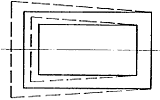
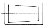
Picture 1 shows an exaggerated view of a problem which may arise. The full lines show the material and the perforated area. The broken lines show the profile after flattening. This profile can, of course, alter depending on the previously mentioned parameter, the perforated area even may not be symmetrical (see picture 1 and 2).
When the material will subsequently be cut to size this problem can be seen, i.e. edge of the perforated area is not running parallel to the edge of the component. If it is considered essential that the sides and ends of the perforated area shall run parallel to the edge of the component the customer should contact us prior to placing an order to exclude any problems which may arise.
Flatness
According to the latest technology perforated plates are roller levelled. Flatness depends on the width of hole, spacing, material thickness and width of edge.
Edge Bows
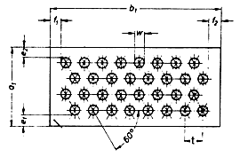
Edge bows may occur on perforated sheets with different side margins (e2>e1) effecting a deviation d between centre and end of the edge of the sheet.
This deviation d is measured at the concave side. It depends on the length, width, thickness, open area, type of material and the relation of e2 to e1.
If the sheets are cut to size after perforation the curved edge only refers to the perforated area.
Wavy Edges
The tensions arising during perforation may cause a deformation of the flatness of the edges, so-called wavy edges, especially if perforated sheets or coils have wide margins or unperforated margins of different widths on either side.
Deviation within the permissible tolerances of the flatness can be guaranteed for perforated sheets and coils with standard perforations and nearly similar unperforated margins on the longitudinal side (width of margin smaller than 2.5 % of the sheet width, maximum 10 mm).
Perforated sheets and coils with wider unperforated margins or with unperforated margins of different widths on the longitudinal side or with special perforations, such as countersunk perforations, embossings etc. tend to considerably higher flatness deviations, especially when using soft material (Al, Cu, CuZn). The acceptable tolerance then needs to be agreed separately.
Blank Side and End Margins
Blank areas
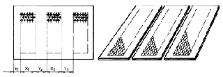
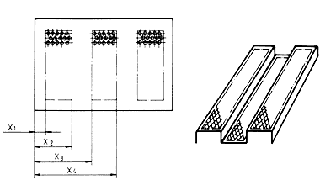
Depending on the application dimensioning should be made as shown in picture 5 or 6.
Special design to avoid cumulative errors: This design is more complex and more extensive.
The requirements have to comply with our capabilities. Tolerance for each value = tolerance for the pitch + tolerance of the feed system.(Repeatability in case of interrupted perforations).
Each single value x depends on the permissible index tolerance, which has to be agreed with us.
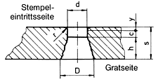
Conical section of hole
If the punch has penetrated deeply enough into the material, the material begins to tear mainly from the cutting side of the matrix.
s = thickness of the sheet
d = hole diameter
D = maximum breakaway diameter
h = height of the breakaway zone
r = turn in radius
y = deformation zone
c = cutting zone
In summary: Tolerances cannot be fixed for the shape and dimensions of the breakaway zone. It can be estimated that the breakaway zone “h” will be between 0.6 x s and 0 depending on the above mentioned components.
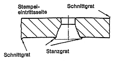
Punching Burr and Shearing Burr
Normal view of drawing (upper side) is the punch entry side. The burr-side is the lower side. Burr-side must be stated explicitely for non-symmetrical plates and sheets with appropriate further processing.
Missing holes / Punch Breakage
Punches may break partly or completely during perforation. The risk of incomplete or missing holes is higher in case of critical conditions of perforation: small holes, stainless steel, maximum open area.
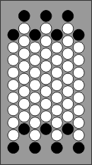
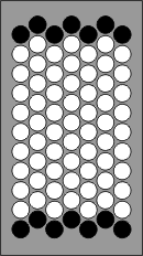
Beginning and end of perforated area
In order to avoid punch breakage the punches are arranged in staggered rows as shown in picture 9, i.e. the first and last row in the direction of feed are incomplete (the black holes show the arrangement of the punches in the tool).
Our aim is to achieve a complete hole pattern at the end of the perforated sheet as shown in picture 10
Cleanliness of the surface – Degreasing – Permissible surface
1. Condition: Directly after processing
Perforated sheets may be slightly lubricated, but without larger accumulations of grease and tallow. There should not leak any oil from the staple.
2. Condition: Degreased sheets
will either be treated with solvents or steam, to remove any traces of grease. Traces of grease should neither remain on the surface nor in the holes. This is the common finish for lacquered sheets or stainless steel products, which will be used directly after processing.Due to the risk of corrosion condition 2 should only be applied with standard steel sheets, in case of a direct further processing.
Standard delivery condition (permissible lubrication)
Condition 1 (directly after processing) is the standard delivery condition as far as there do not exist any other regulations.
For condition 2 rust protection requirements might be agreed, together with an effective adequate storage period.
Delivery condition for sea transport (even for a short time) has to be specified.
Surface finish
A slight surface defection due to machine processing cannot be excluded. Please contact us if you need a perfect surface!
Technical Informations
Standards and sizes
Standards
Length and Width
Material Thickness
Squareness of cut plates
Parallelism
Flatness
Edge Bows
Wavy Edges
Blank Side and End Margins
Blank areas
Conical section of hole
Punching Burr and Shearing Burr
Missing holes / Punch Breakage
Beginning and end of perforated area
Cleanliness of the surface – Degreasing – Permissible surface
Surface finish
Hole Shapes
Round holes
DIN 24 041
RV round holes, staggered rows
RD round holes, diagonally staggered rows
RG round holes, straight rows
Square holes
DIN 24 041
QV square holes, staggered rows
QD square holes, diagonally staggered rows
QG square holes, straight rows
Hexagonal holes
DIN 24 041
HV hexagonal holes, staggered rows
Oblong holes
DIN 24 041
LV Oblong holes, staggered rows
LG Oblong holes, straight rows
LGE Oblong holes, straight rows, square


